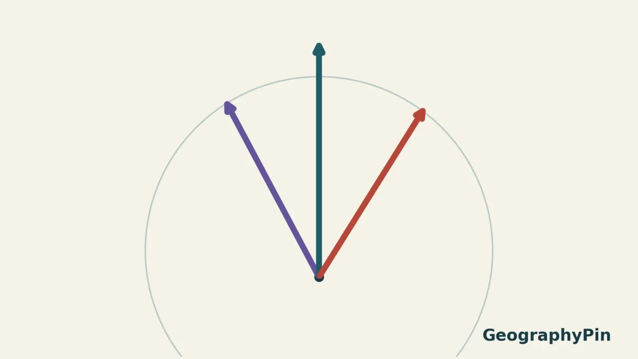
A map can show three north arrows without contradicting itself. Each arrow answers a different question: which way follows a geographic meridian, which way a magnetic compass aligns, or which way the map’s coordinate grid runs.
True north follows the local meridian toward the geographic North Pole. Magnetic north follows the horizontal direction of Earth’s magnetic field at your location. Grid north follows the northward lines of a projected coordinate grid. Their differences depend on where you are, the grid used and, for magnetic north, the date.
How to use this article: Understand what a compass senses, distinguish the two angular differences, or compare one target’s three bearings.
1. Three north references, three different jobs
The word “north” needs a reference when an angle matters. A bearing is measured from a chosen starting direction; changing that starting direction changes the number even when the target stays in exactly the same place.
| Reference | Meaning | Common misunderstanding |
|---|---|---|
| True north | The northward direction along the local geographic meridian | It is not necessarily the top edge of every map. |
| Magnetic north | The horizontal field direction followed by a compass, away from interference | It is not a straight-line pointer to one fixed magnetic pole. |
| Grid north | The northward direction of the map’s projected grid | Grid lines need not follow geographic meridians. |
On many USGS topographic maps, a star marks true north, GN marks grid north and MN marks magnetic north. The symbols are a map-reading convention, not a universal interface used by every publisher. Read the key rather than assuming that any upward arrow means magnetic north.
For the wider workflow of symbols, scale and terrain, use our map-reading guide. Here the narrower question is why those north references can disagree and how that affects the meaning of a bearing.
2. Why a compass does not simply point at a pole
A compass responds to the field where it sits
A freely turning magnetic needle responds to the local magnetic field. For a compass held horizontally, the relevant direction is the field’s horizontal component. NOAA explicitly cautions that a compass does not point toward a single geographic point called the magnetic pole.
That distinction matters because Earth’s magnetic field is more complicated than a perfectly aligned bar magnet. Its direction varies across the planet and changes with time. A diagram showing a magnetic pole somewhere in the Arctic cannot, by itself, supply the compass correction for a particular place.
Magnetic declination is the angle between magnetic north and true north. Under NOAA’s convention, an eastward declination is positive and a westward one is negative. A value without a location and date is incomplete for real use. An old map’s printed value describes its stated reference time, not a permanent property of the landscape.
Local interference is a separate problem. Nearby electrical systems or magnetic material can affect a compass. Updating a regional declination value does not remove an instrument’s local disturbance. Likewise, the three-arrow diagram below explains references; it is not a calibration procedure for a particular compass or phone.
3. Why grid north can differ from true north
Grid north comes from cartography rather than magnetism. A projected map places geographic positions on a flat coordinate system. The northward grid direction can differ from the local meridian because the projection does not keep every meridian aligned with the same parallel set of grid lines.
The true-to-grid difference is often called grid convergence. Its size depends on the projection and the location within it. It is not a compass error, and an updated magnetic model does not eliminate it. Changing the coordinate grid can change the reference even though the ground and magnetic field have not changed.
Declination and the grid–magnetic angle are not interchangeable
Declination compares magnetic north with true north. A map-to-compass comparison may instead need magnetic north relative to grid north. Those are equal only when true north and grid north coincide at the location concerned. Naming the pair of arrows is more useful than remembering an unexplained correction number.
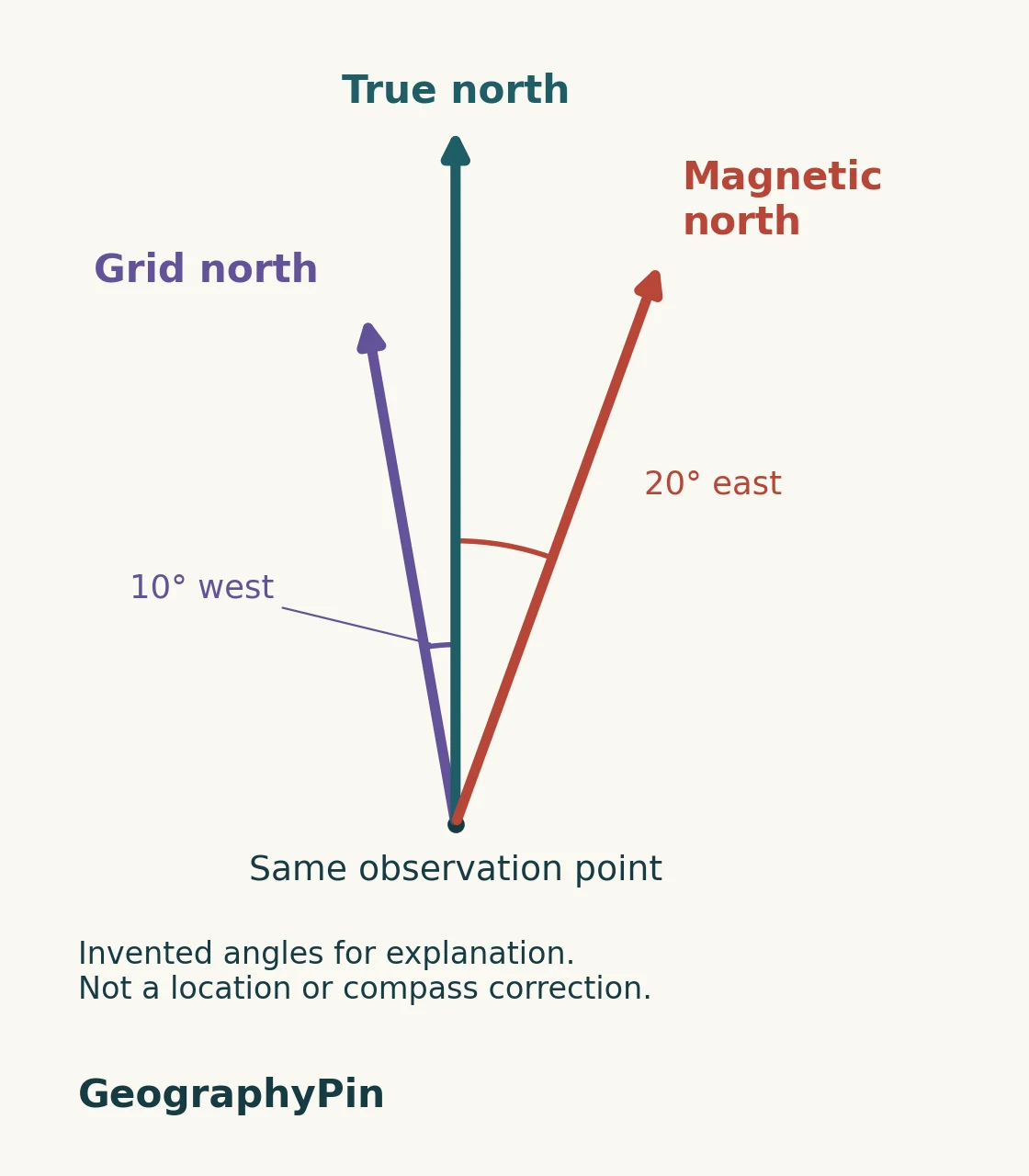
The ordering of the arrows is not universal. Elsewhere, magnetic north could lie on the other side of true north, or grid and true north could coincide. Arrow lengths in this conceptual illustration have no physical meaning; the angles between directions carry the information.
4. One direction can have three different bearings
A hypothetical target, not field instructions
Keep the invented north directions above and place a target at a true bearing of 60°. All bearings in this example are measured clockwise from their named north reference.
| Reference used | Target bearing | Reason |
|---|---|---|
| True north | 60° | The target direction is defined this way. |
| Magnetic north | 40° | Its starting arrow is already 20° clockwise from true north. |
| Grid north | 70° | Its starting arrow is 10° counterclockwise from true north. |
The three numbers do not identify three destinations. They describe the same direction from different zeros. In the stated east-positive convention, the true bearing equals the magnetic bearing plus declination: 40° + 20° = 60°. Reversing that conversion requires reversing the operation. A westward declination would carry a negative sign.
For the grid comparison, the diagram is enough: starting 10° west of true north adds 10° to the clockwise angle needed to reach this target. We do not attach an unexplained positive or negative “convergence” number because software and surveying conventions must be checked before applying a sign rule.
This is why “always add” is not a complete instruction. You must know which reference you start with, which reference you want, and how the correction’s direction is expressed. A device may already apply a correction; applying the same adjustment again would change the answer unnecessarily.
5. What to check before using a north correction
Before interpreting a map’s north diagram, identify its grid and the date associated with its magnetic information. Then check whether your instrument or app reports true, magnetic or grid bearings. Similar-looking numbers are not directly comparable if their reference directions differ.
For a real location, NOAA’s geomagnetic tools provide date- and position-dependent information. A magnetic model is not a timeless universal number: use the model and input requirements stated by the provider. The World Magnetic Model also has a defined validity interval and limitations. This article does not calculate or certify a local declination.
Do not extrapolate an old printed annual-change figure indefinitely or borrow another region’s correction. For practical navigation, use current local information, the map’s instructions and your equipment’s guidance. This explanation establishes the concepts; it does not replace training, equipment checks or a location-specific navigation plan.
Frequently Asked Questions
Can all three north directions coincide?
Yes. True and grid north can coincide at some locations, and the magnetic declination can also be zero. That coincidence depends on the grid, location and date; it is not a permanent worldwide alignment.
Is magnetic declination the same as magnetic inclination?
No. Declination compares horizontal directions: magnetic north and true north. Inclination, also called magnetic dip, describes the field’s angle relative to the horizontal. They are different components of the magnetic field.
What Did We Learn Today?
North can mean a geographic direction, a local magnetic-field direction or a grid direction. Declination relates magnetic to true north; a grid–magnetic correction compares a different pair. The hypothetical target shows why one physical direction can have several correct bearing numbers. Name the reference before interpreting the number, and keep changing magnetic information separate from projection geometry.
Sources & Data Notes
The GeographyPin diagram is an original conceptual illustration, not a magnetic-field map or a surveyed north diagram. Its 20° east and 10° west values were chosen solely to explain the arithmetic. No location, date-specific field prediction or model output is implied. The bearing example explicitly uses clockwise bearings and east-positive magnetic declination; real map and instrument conventions must be checked.
- NOAA/NCEI: Magnetic Declination — definition, sign convention, local-field direction and conversion.
- USGS: What do the different north arrows on a topographic map mean? — symbols and projection-dependent grid north.
- USGS: What is declination? — changing field and dated map information.
- USGS: How does a compass work? — local interference.
- Ordnance Survey: Compasses and Directions — the three north references.
- NOAA/NCEI: Geomagnetism Frequently Asked Questions — magnetic inclination and field components.
- NOAA/NCEI: World Magnetic Model — model validity and tools.